Getting to know the printer & simple calibration
To start off the project, I wanted to get to know the printer better and understand the basis of the build. The printer works quite well with simple scripts for basic shapes like tubes, but when you start printing complicated models with lots of movement, things get inaccurate.
The problem
The printer has systematic errors in its positioning. When the print-head rotates, it doesn’t end up exactly where the G-code tells it to go. Small mechanical imperfections, assembly tolerances, and maybe some flexibility in the 3D printed parts all add up. For complex geometries with lots of movement and rotations, the errors compound.
My calibration approach
I needed a way to measure and correct these errors. Here’s what I did:
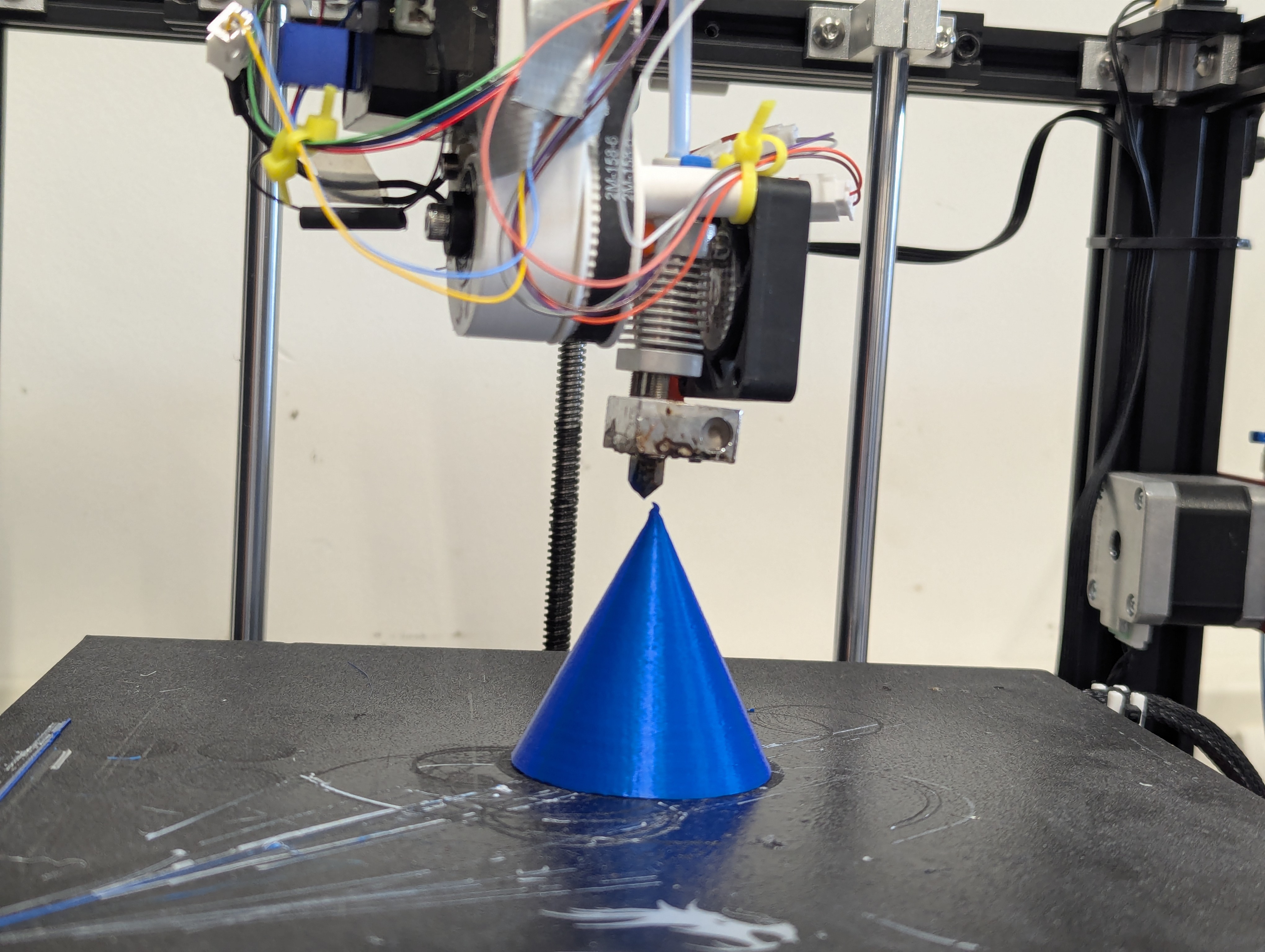
I printed a cone and positioned the print-head where the tip should be according to the G-code. Then I manually moved it to where the tip actually was and noted the offset. I did this for different angles on both the A-axis (rotation around Z) and B-axis (tilt).
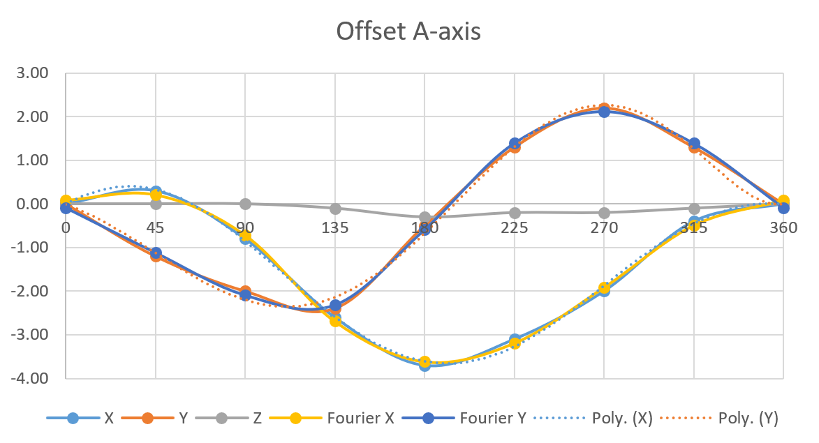
The A-axis showed cyclic errors, which makes sense for rotational movement. X corrections ranged from +0.3mm to -3.7mm, Y corrections from +2.2mm to -2.4mm. The pattern repeated every 360 degrees, as you’d expect.
View A-axis measurement data
| Angle | Error X | Error Y |
|---|---|---|
| 0° | 0 mm | 0 mm |
| 45° | +0.3 | -1.2 |
| 90° | -0.8 | -2.0 |
| 135° | -2.6 | -2.4 |
| 180° | -3.7 | -0.5 |
| 225° | -3.1 | +1.3 |
| 270° | -2.0 | +2.2 |
| 315° | -0.4 | +1.3 |
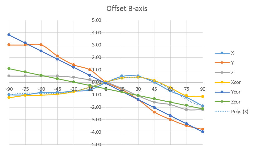
The B-axis had different error patterns. Since it only tilts from 0 to 90 degrees, the errors were more linear.
View B-axis measurement data
| Angle | Error X | Error Y | Error Z |
|---|---|---|---|
| -90° | -1.00 | +3.0 | +0.50 |
| -75° | -0.99 | +3.0 | +0.50 |
| -60° | -0.80 | +3.0 | +0.50 |
| -45° | -0.80 | +2.1 | +0.50 |
| -30° | -0.70 | +1.4 | +0.40 |
| -15° | -0.60 | +1.0 | +0.19 |
| 0° | 0 mm | 0 mm | 0 mm |
| 15° | +0.50 | -0.6 | -0.51 |
| 30° | +0.50 | -1.4 | -1.10 |
| 45° | 0.00 | -2.4 | -1.60 |
| 60° | -0.70 | -3.0 | -1.80 |
| 75° | -1.21 | -3.5 | -2.20 |
| 90° | -1.90 | -3.8 | -2.20 |
Finding the right correction method
First I tried fitting a polynomial function to the data that Excel automatically generates when creating a trendline on a scatter plot. Excel gave me a nice-looking curve, but it didn’t work outside the calibration range. At 315 degrees, it wanted to correct by 24mm when the actual error was only 0.4mm. Polynomials are terrible for extrapolation.
The A-axis errors are cyclic and repeat every 360 degrees. Fourier series are well-suited for representing such periodic behaviour. Using just three harmonics, I got the average error down to 0.09mm across all calibration points.
For the B-axis, simpler fits worked fine. Linear for Y and Z, 6th-order polynomial for X (B stays within 0-90 degrees where the polynomial behaves).
The Python script
I wrote a Python script that reads G-code, finds lines with A or B movements, applies the correction formulas, and outputs corrected G-code. When both axes move in the same line, it combines the corrections additively.
What’s your take?
I’m curious if anyone has other ideas for calibrating multi-axis printers. This cone-tip method worked, but it’s tedious. Some alternatives I’m considering:
- Using a touch probe for automatic calibration
- Computer vision to track nozzle position
- Different test shapes that might reveal errors better
Please leave a comment if you have any input on this or join the Discord to have a chat!
Comments